

Best Practices Guide for Perimeter Security Applications
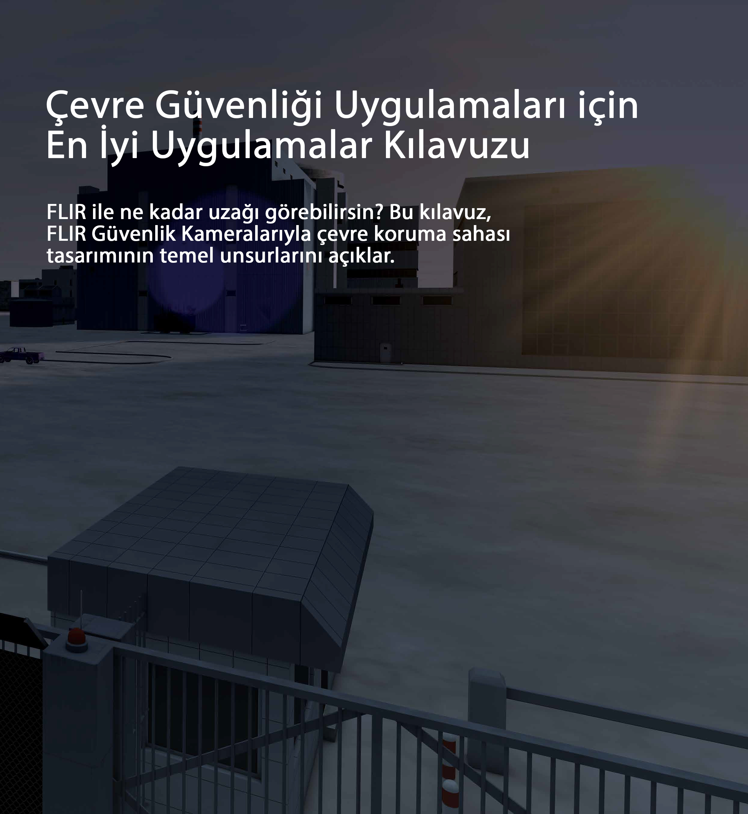
Where to start
The basic concept of designing an environmental protection application involves creating a virtual line that separates the outdoor areas from the indoor areas. In most cases, the moment a target crosses the virtual line from an external area to an internal area is considered an intrusion. However, in some cases it is also necessary to detect targets entering the virtual line or moving within a predefined internal area.
To determine design parameters such as camera placement and height, lenses and distances, several calculations are required to ensure that the following conditions are met:
- There must be sufficient coverage along the virtual line to eliminate any "dead zones" where a potential target is not completely covered by the security camera's field of view.
- Target size verification must meet the performance criteria required by the video analysis of a particular camera, from the closest to the farthest points covered by each of the cameras along the fence line.

Various tradeoffs apply between target size and scope. In general, expanding the camera's coverage results in smaller targets in the field of view. Therefore, the best way to start is with the application requirements:
• Does the app require detection or recognition? Does it have to distinguish between people and vehicles?
• What are the important alarm scenarios? Should an alert be triggered when a target crosses or approaches the virtual line?
• Do I prefer performance over costs? The probability of detection increases as more cameras are used, allowing for overlapping coverage. On the other hand, it is often possible to use fewer cameras and still guarantee high performance.
Camera placement
There are several ways to achieve optimum area coverage and fence line protection when determining camera placement. Best practices consider the specific environment, application requirements, and site topology. However, in most cases optimum performance and efficiency are achieved by placing the cameras so that their field of view is parallel to the fence line and perpendicular to the movement of potential intruders approaching the perimeter or crossing the border.
The highest detection probability and lowest false alarm rate are achieved when targets move horizontally from one side of the camera image to the other within the camera's field of view. The following are considered best practices for camera positioning to ensure full camera coverage throughout the perimeter.
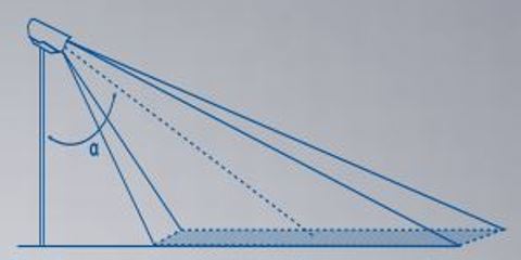
• Install the camera at a height of 4 meters (13 ft) or higher
• Point the camera towards the ground with a tilt angle in the range of 45-60 degrees (the tilt angle is defined as the angle measured between the camera mast and the center of the camera's field of view)


• In setups with multiple cameras, the cameras must overlap to eliminate any dead zones where the camera cannot see the target "from head to toe".
• For optimum performance, position the cameras so that their field of view is parallel to the fence line and perpendicular to the movement of intruders, rather than pointing the cameras towards approaching targets.
• Position cameras so that their field of view sees as little of the horizon line as possible. When determining camera position, consider whether you only need to detect the moment of intrusion or if a target is approaching an area.
• Make sure the cameras are mounted on stable poles with minimum vibration and maximum resistance to wind.
Choosing the right lens
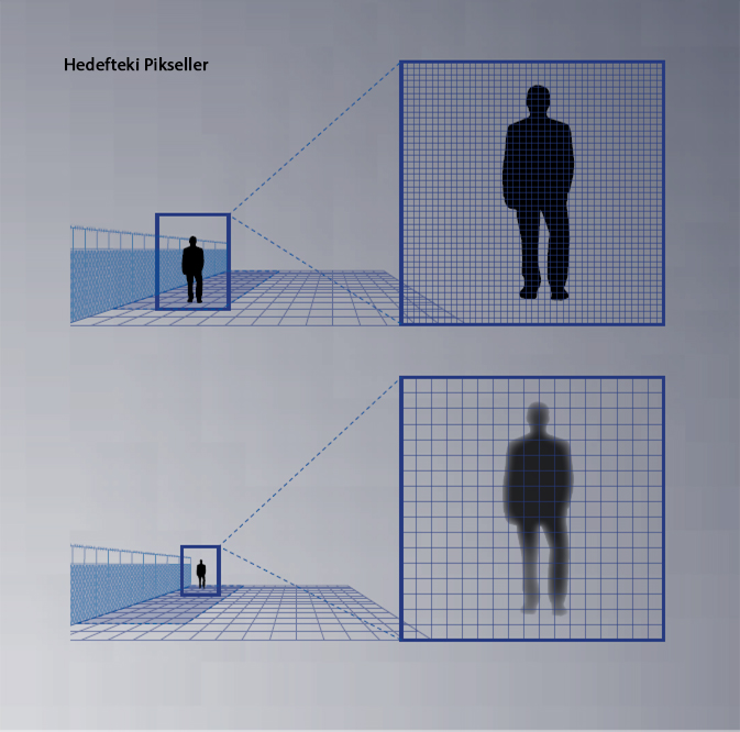
The main thing to consider when choosing a lens is focal length, which has a significant impact on both the camera's field of view and target size. A larger focal length increases the magnification of objects in the field of view, to be represented by a larger number of pixels. In other words, larger focal length means larger targets for video analytics, resulting in greater detection distance. See Figure 5.

On the other hand, the correlation between focal length and field of view is the opposite: the smaller the focal length, the wider the field of view. See Figure 6. This means that the trade-off between detection distances and the width of the scene must be taken into account when choosing the appropriate lens. In most cases, best practice is to define the minimum requirement for scene width and choose the largest available focal length to meet the width criteria.

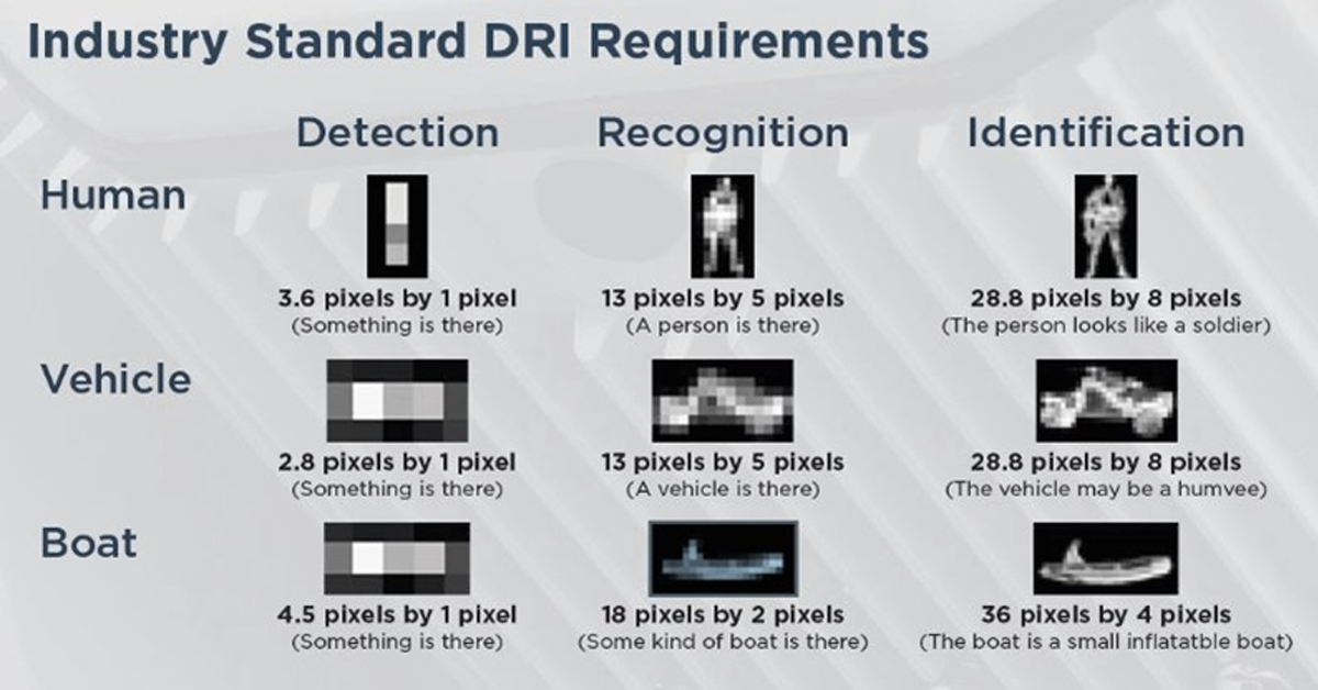
Target size and detection range
Target size is a term used to calculate the maximum distance at which a FLIR camera with built-in analytics can detect a target. This distance is also called the “sensing range.”
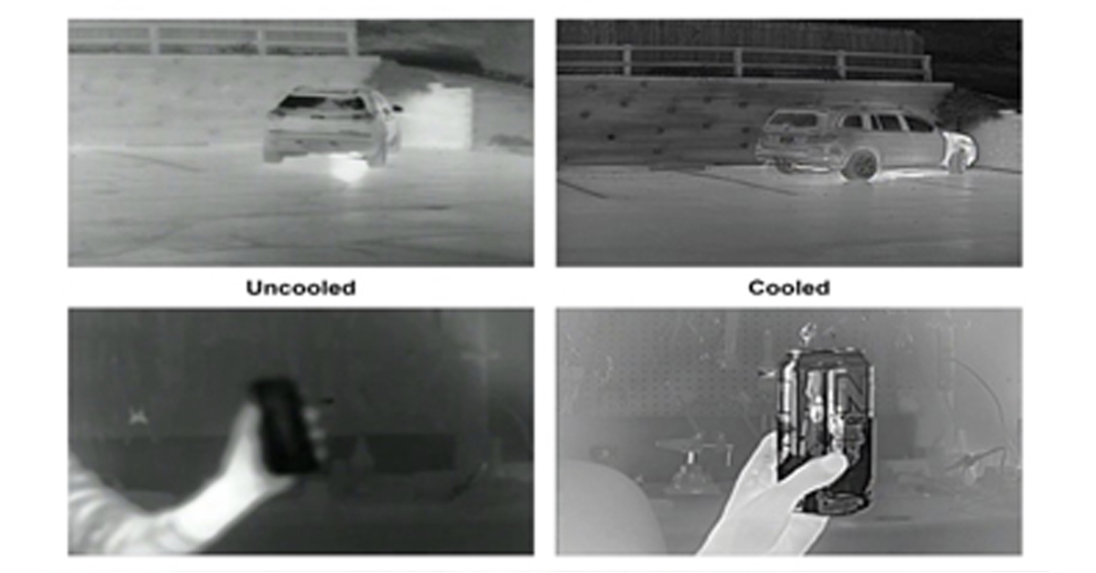
Target size is determined by the number of pixels representing the target in the camera image and is also known as "Pixels on Target" (POT). Besides the critical factor of target size, detection range criteria also depend on numerous environmental and system variables, including background temperature (hot desert and cold snow) and atmospheric conditions (clear skies and fog). Both directly affect the contrast level of the scene, the visibility of the target, the ability to understand the nature of the target (moving vehicle vs. creeping person), speed and movement.
Therefore, the determination of detection ranges should be treated as a statistical evaluation that takes these additional factors into account. As a best practice, the following formula is provided to calculate the detection range under optimum conditions where relevant factors do not adversely affect the performance of the detection range of the internal video analytics. In other words, detection under optimal conditions reflects the maximum distance that can be reached in practical scenarios.
In addition to detection, the formula can be used to calculate classification intervals under optimum conditions. The difference between detection and classification is that while detection results in alarms triggered by human or vehicle targets, classification allows it to distinguish between the two and configure the system to generate an alarm for certain types of targets while ignoring others.
FLIR offers an online, easy-to-use product planning tool called Raven, which is a convenient way to calculate target size / POT at any distance for any FLIR thermal camera model. Determine the detection or classification range based on the maximum distance where detection or classification criteria are met.


Using existing satellite imagery, the Raven Site Planning Tool allows users to simulate the placement of FLIR cameras in highly accurate, coordinate-controlled locations.
The table below can be used as a quick reference for FC-Series ID camera line detection and classification distances.
Classification Range

Detection Range

Blog Posts
Thermal Camera Selection
How Far Can I See?

How Should Human Temperature Be Measured?

What is Wide Dynamic Range?

MYNOISE AUDIO MIXER REVIEW

WHAT IS A WIRELESS DISTRIBUTION SYSTEM?

POE VS. POE+ VS. POE++: CHOOSING THE RIGHT INDUSTRIAL ETHERNET SWITCH FOR YOU
INDUSTRY-LEADING INDUSTRIAL ETHERNET SWITCHES

UNDERSTANDING WHAT THE INDUSTRIAL INTERNET OF THINGS IS
THE DIFFERENCE BETWEEN A HUB, SWITCH, & ROUTER
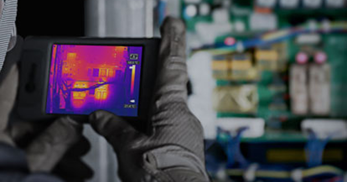
5 Benefits of Thermal Imaging Cameras

DIFFERENCE BETWEEN INDUSTRIAL ETHERNET AND REGULAR ETHERNET

INDUSTRIAL NETWORKING EQUIPMENT USED FOR AUTONOMOUS VEHICLES

CYBERSECURITY: PROTECTING INDUSTRIAL CONTROL SYSTEMS

HOW INDUSTRIAL NETWORKING CAN PROVIDE SECURITY FROM DRONES
.webp)
Thermal Cameras Reveal How to Keep Your Home Cool During a Heat Wave

FLıR ONE PRO
.png)
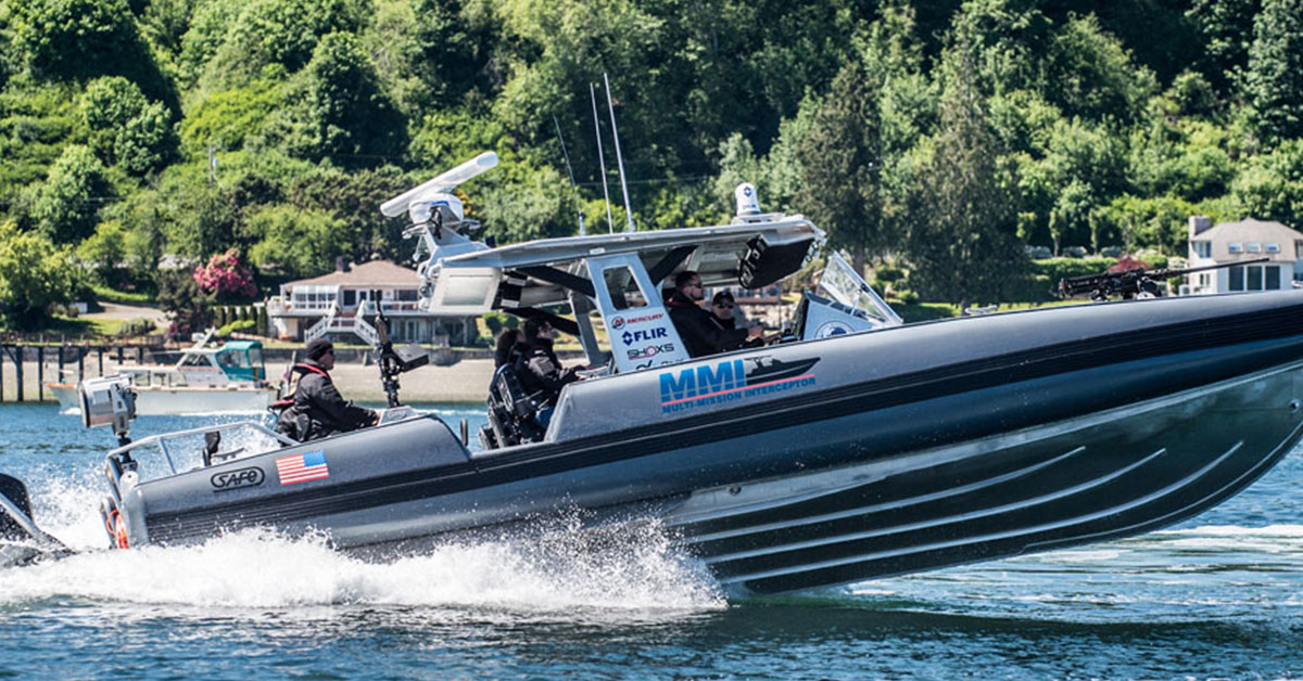
Unmatched Maritime Awareness with Cooled Thermal Imaging
.png)
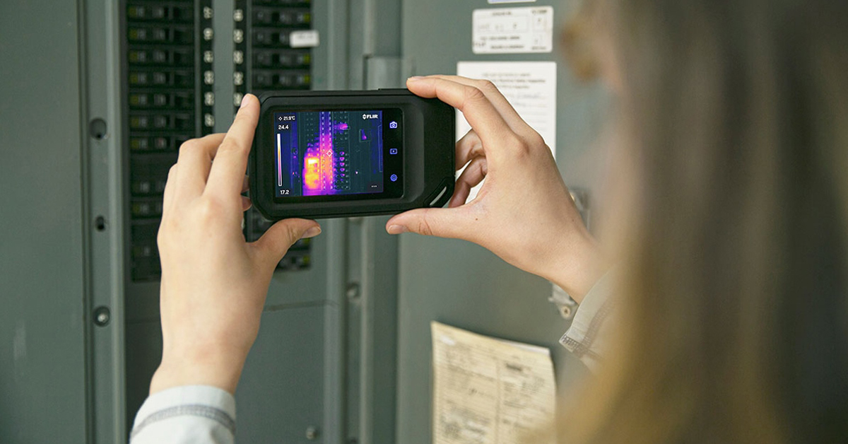
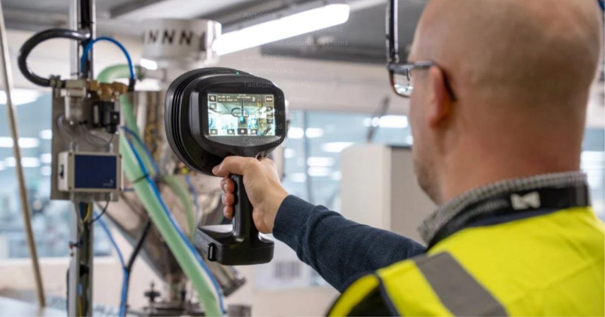
What Is the Right Handheld Thermal Camera for You?
.png)
Camera Resolution and Range
.png)
Special Applications for Marine Cameras
.png)
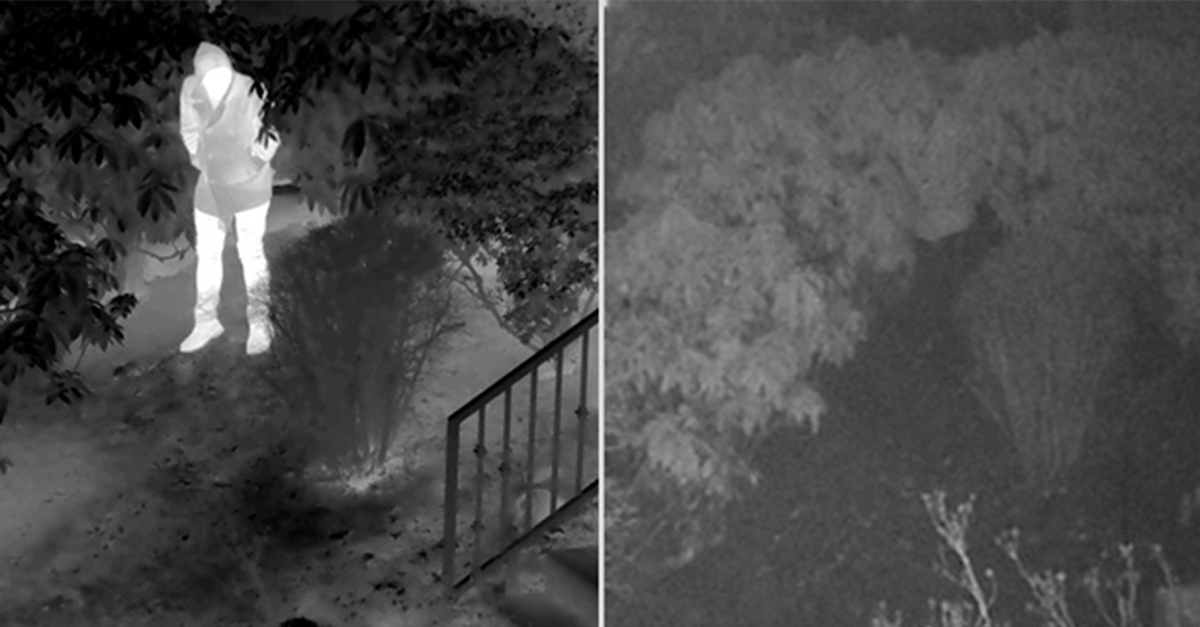
What’s The Difference between Thermal Imaging and Night Vision?
.png)
Can Thermal Imaging See Through Fog and Rain?
Which Cx-Series Camera Is Right for You?
.png)
What is MSX®?
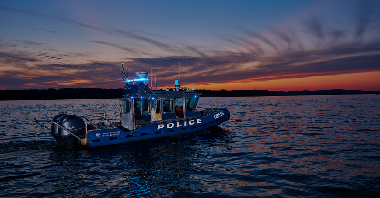
Five Reasons Maritime First Responders Need Thermal Imaging
.png)
3 Distinguishing Features of Superior Thermal Cameras
.png)
Determine Which Visible and Thermal Security Cameras You Need
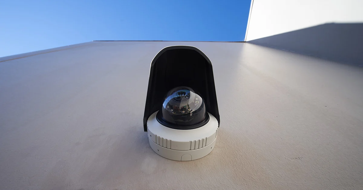
Bullet vs. PTZ vs. Dome: Which Security Camera Is Right for You?

Interfaces for Machine Vision

Machine Vision Sensor Review
.png)
Teledyne FLIR, the Industry Leader, Launches Boson +, a Long-Wave Infrared Thermal Imager Module with an Accuracy of Less Than 20 mK
.png)
Whitepaper: IP-Based Security Convergence
.png)
3 Technologies Transforming Safe Cities into Smart Cities
.png)
Insights from the Field: Ensuring Workplace Safety Using Thermal Camera Screening for Entry Control

Thermal Night Vision as a Force Multiplier

Can Thermal Imaging See Through Walls? And Other Common Questions
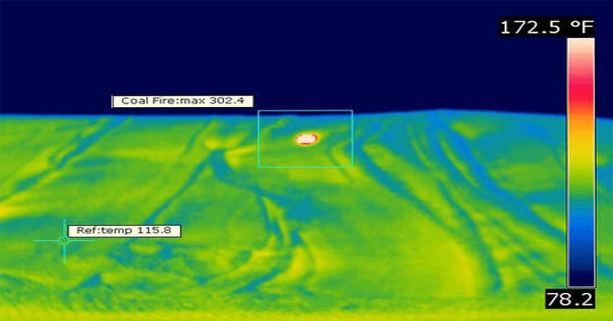
Application Spotlight: Early Fire Detection for Rapid Heat Generation

Protect Personnel and Equipment by Detecting Early Signs of Fire
Teledyne FLIR Launches A500f/A700f Cameras for Fire Detection and Condition Monitoring
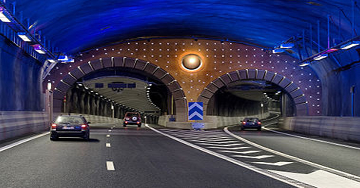
Thermal Imaging Cameras Help Guarantee Fire Safety in Tunnels
Thermal Imaging Cameras Help to Prevent Fires

ITS-Series Dual AID Surpasses Standards for Fire Detection Systems in Japan
How Layering Multispectral PTZ Cameras and Radars Improve Perimeter Protection
POWER REMOTE RESET TECHNOLOGY - PRRT

Why Yacht Owners are Adding Thermal Imaging Cameras to Minimise the Risk of Lithium-Ion Battery Fires?
.png)
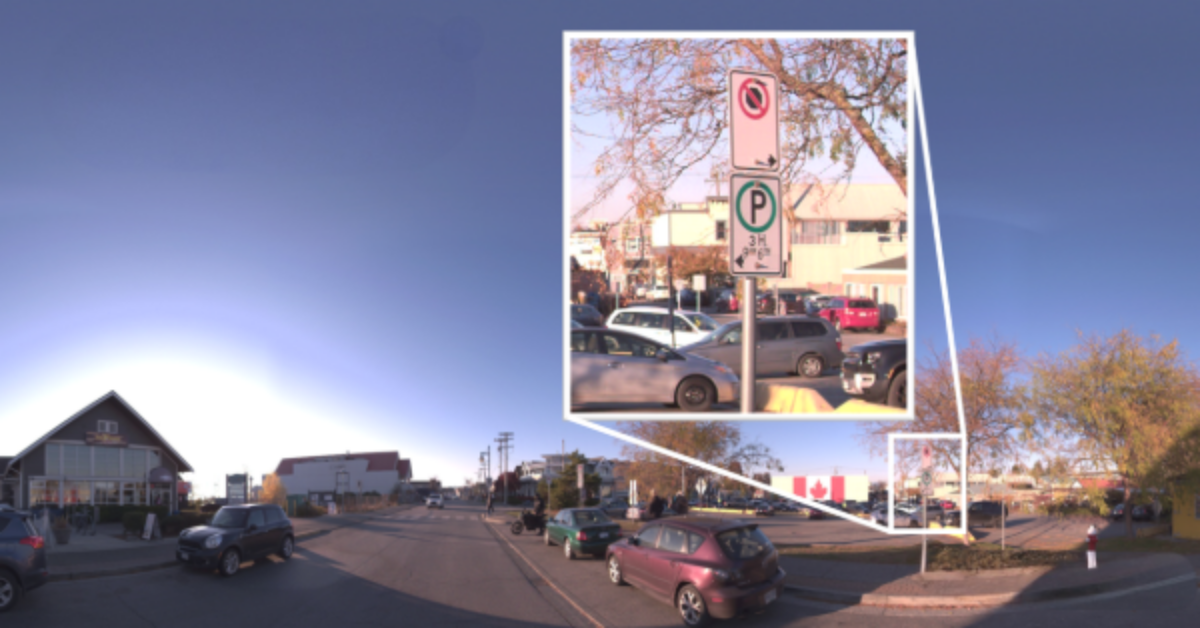
Intelligent Transportation Systems

Best Practices Guide for Perimeter Security Applications

Protect Pedestrians, Bicyclists and More with Thermal Smart Sensors
White Paper: Application of Ground-Based Security Radar to Perimeter Systems

What is Thermal Leakage and How to Reduce Its Risks
Battery Inspection Using Advanced Thermography

Providing ire Protection for Lithium Battery Storage
The Power of Thermal Imaging
.png)
Why Panel PCs Are Perfect For Industrial Applications?

Teledyne DALSA
.png)
Advantages of Virtual Barrier Video Analytics for Perimeter Security Systems
.png)
.png)
NASA Takes the Teledyne FLIR Boson Thermal Camera Module Out of this World
.png)
Port Security Enhancement: DP World Yarımca's Trust in FLIR Security Solutions for Effective and Safe Port Operations
.png)
The Importance of Thermal Sensitivity (NETD) for Detection Accuracy
.png)
Bosphorus Boat Show 2025: The Meeting Point of the Maritime World

Application Spotlight: Critical Asset Monitoring for Thermal Conditions
.png)
Thermal Imaging for Marine Firefighting
Imaging in Mobile Mapping
.png)
Using Thermal Imaging for Oil Spill Detection

Five Reasons Maritime First Responders Need Thermal Imaging
Case Study: Tackling Compressed Air Leaks in Automotive Parts Manufacturing with Acoustic Imaging
Thermal Night Vision as a Force Multiplier
.png)
Line Scan Contact Image Sensor - AxCIS
Beyond Resolution: What Really Makes a Camera System Work for Mobile Mapping
.png)
Multispectral Marine Cameras for USV Applications
.png)
Stabilizing FLIR Cameras for Smooth Viewing in Rough Waters
 (1).png)
Enhancing Maritime Safety with Video Tracking & Radar Integration

